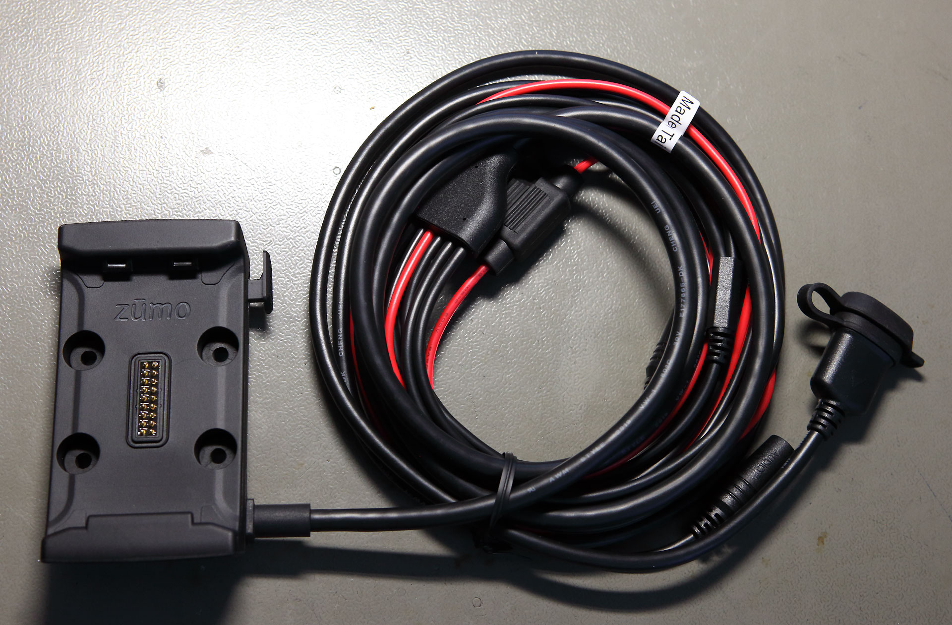
I recently purchased Garmin Zümo 595LM. The cradle, as it is, contains very bulky set of cables, which I don't actually need, like three audio connectors (two 3.5 mm and one 2.5 mm jacks):
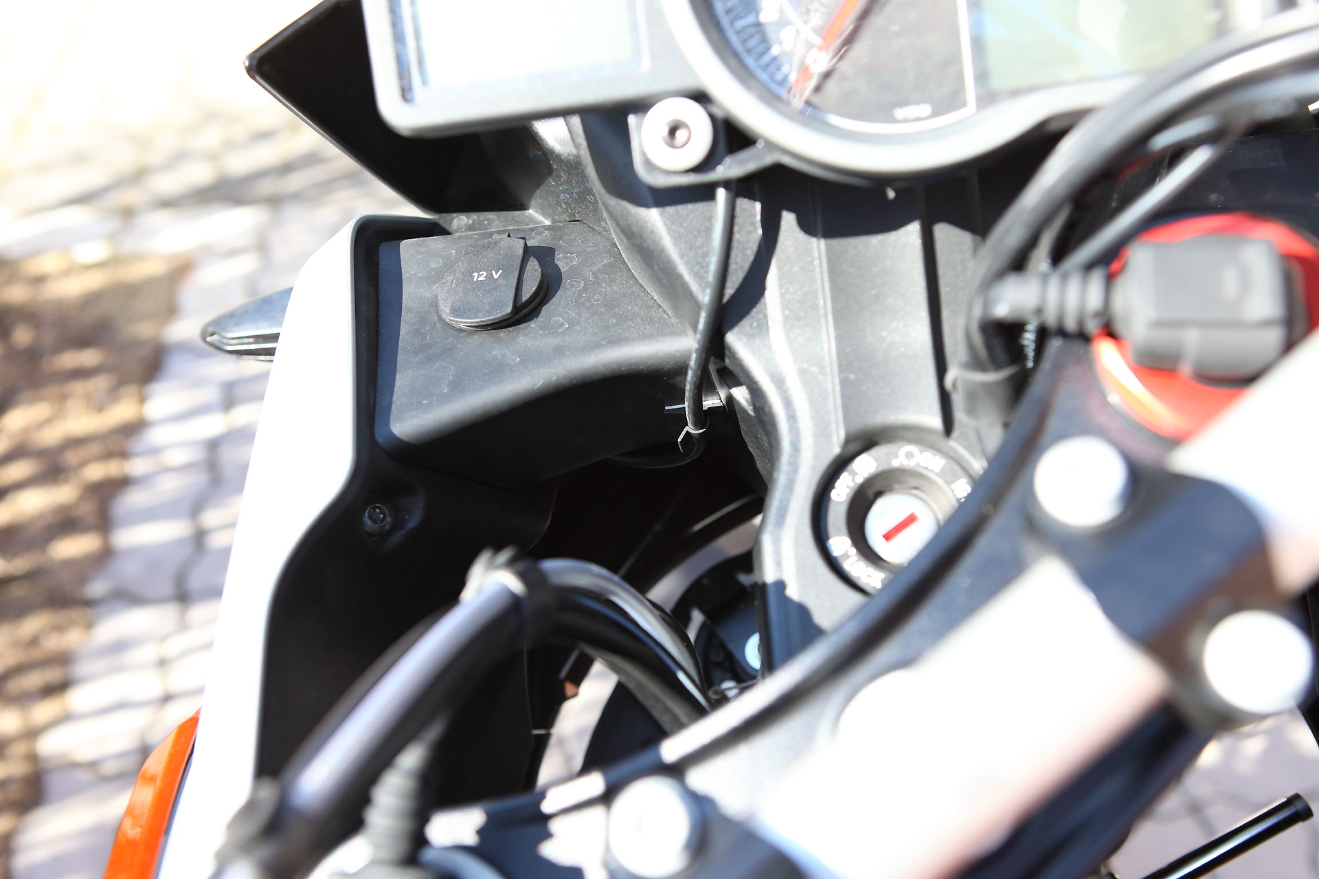
I need just the power feed from my bike for the Zümo, and even that cable can be quite short since my main bike (KTM Adventure 1190) has power connectors for the accessories behind the headlight, and you can install the cradle just behind the windscreen using KTM powerparts mount. So something needs to be done to make this cradle usable for that. This page is for documenting the findings so everyone doesn't need to start from scratch.
The cradle is, I believe, the same than for Zümo 590.
Garmin, if you are reading this, Please, make a simplified version of this cradle or put a connector in the cradle so it is possible to use just the power input without any other cables, so we end users don't need to start hacking right away. Not everybody is comfortable with modifying electronics stuff.
Of course, the standard disclaimer is that if you do any modifications, I will not be responsible if you damage your cradle or Zümo or anyhing else during the process, so proceed with caution, and always check before connecting if anything you'll find here, makes sense in your case. Don't do it if it doesn't seem to make sense!
This document applies to Garmin cradle 011-03386-00. On the PCB inside, markings are 105-02349-00 VER 6.
I don't go into very detail how to do this, but you can find descriptions at advrider.com. There is also a video at YouTube (unfortunately for most of us, in Flemish, but fortunately, the pictures are universal). There are some good hints for the bending protection grommet and other parts in that video and description.
To open the cradle, you must unscrew 7 Torx T5 screws (someone mentions at above topic that they were T6, so to avoid stripping of the screw head, try first with T6 and if it doesn't fit, then T5) at the back of the cradle. Be careful not to loose the release latch lever and spring when removing the back.
The wire harness end is sealed with somekind of siliconish glue. You can remove the sealant using small flat-headed screwdriver quite easily. Be careful not to damage the wires if you are going to reuse the wires.
There is also a small staple-like holder on the top of the harness main strain relief. You must pry that off with a flat-headed screwdriver or similar to be able to pull the harness off.
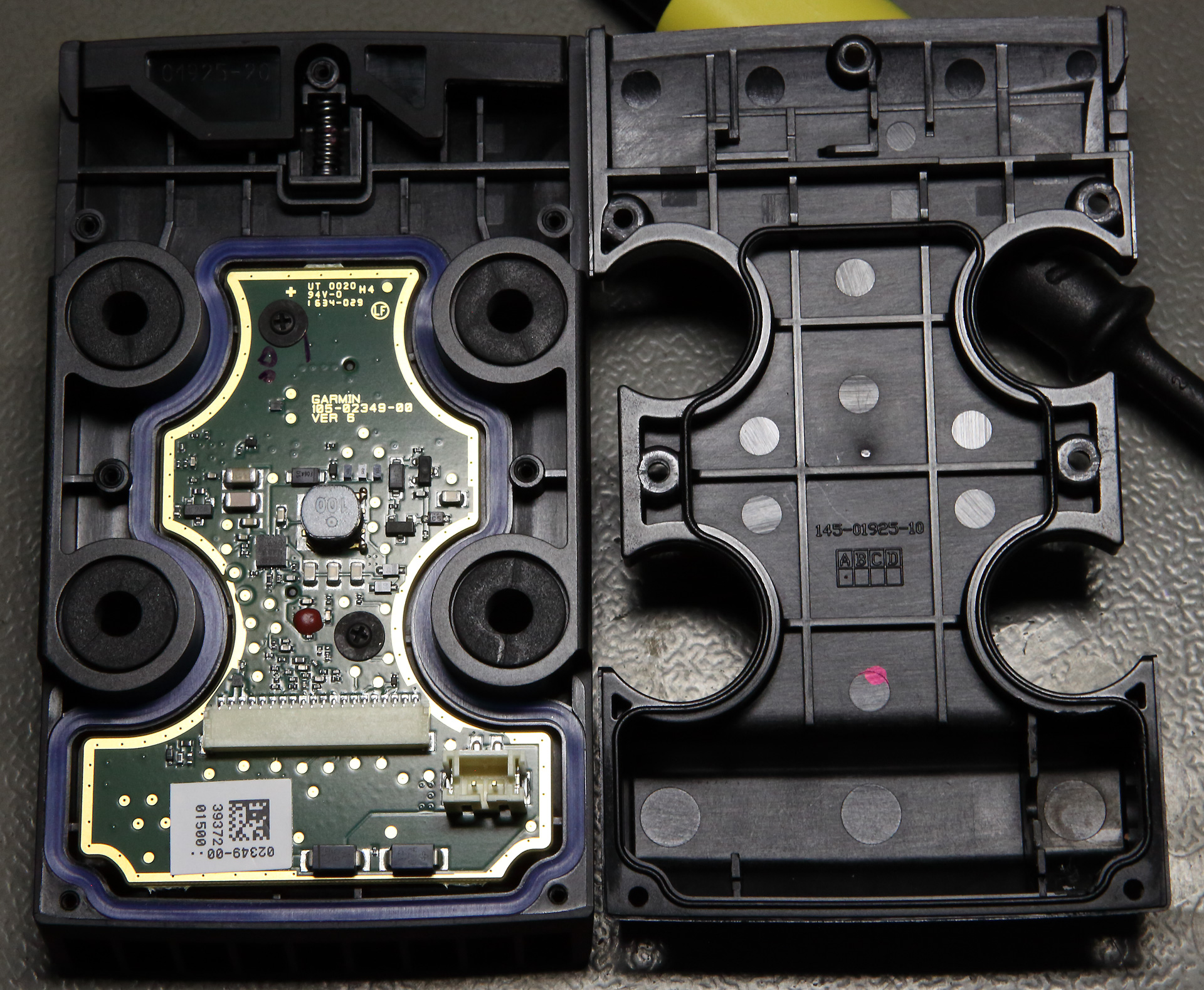

If you look carefully at the 20-pin connector, you'll find out that the pin 1 is marked with a small arrow at the left side in the picture.
Connector type is JST SH, 20 pin (1.0 mm pitch), protruded version. You can get housing type SHR-20V-S-B from Digi-Key, part number 455-1391-ND or from Farnell, part number 1830835. Contacts are JST SSH-003T-P0.2, and Digi-Key part number is 455-1561-2-ND or Farnell 1679142.
| Pinout table for 20-pin signal connector | |||
|---|---|---|---|
| Pin number | Wire color | Function | Notes |
| 1 | Black | USB VBUS | Connected together with pin 4. |
| 2 | Green | USB D+ | |
| 3 | White | USB D- | |
| 4 | Red | USB VBUS | Connected together with pin 1. |
| 5 | Yellow | Audio out switch | Connected to audio out tip when no plug is inserted. |
| 6 | Magenta | Audio out ring | Right channel |
| 7 | Orange | Audio out sleeve | Audio out ground |
| 8 | Brown | Audio out tip | Left channel |
| 9 | N/A | N/A | |
| 10 | Blue | Mic in | |
| 11 | White | Mic GND | |
| 12 | N/A | N/A | |
| 13 | Yellow-white | Audio in switch | Connected to audio in tip when no plug is inserted. |
| 14 | Magenta-white | Audio in ring | Right channel |
| 15 | Orange-white | Audio in sleeve | Audio in ground |
| 16 | Brown-white | Audio in tip | Left channel |
| 17 | N/A | N/A | |
| 18 | N/A | N/A | |
| 19 | N/A | N/A | |
| 20 | N/A | N/A | |
You might notice that there is no USB GND on the table above. It seems that power connector GND is used also for the USB GND. USB VBUS (or +5 power) has two wires, probably to compensate the resistance of relatively thin wires. So if you want to connect the USB power, then you must use the power connector GND for USB GND.
It seems that audio switches are not at least directly connected to pogo pins which connect to the Zümo itself. So you don't need to do any extra loopings to signal connectors. But to be as transparent as possible, if you want to make simple "power only"-cradle, you should connect audio switch pins so that they are in closed position (connect together pins 5-8 and 13-16). If you want to be sure and to do this, then you can get pre-made jumper wires from Digi-Key, 455-3075-ND, which you can use with empty SH connector housing.

Connector type is JST PH, 2 pin (2.0 mm pitch). Housing type is PHR-2 (Digi-Key part number 455-1165-ND, or Farnell 3616186). Crimp contacts are SPH-002T-P0.5S (Digi-key part number 455-1127-2-ND or Farnell 1671245).
It seems that there are plenty of cheap pre-crimped stub cables available for the power connector on Ebay, so I don't think it makes sense to start from plain housing and crimp contacts unless you have a very specific need for that. So above is mostly for convenience.
| Pinout table for 2-pin power connector | |||
|---|---|---|---|
| Pin number | Wire color | Function | Notes |
| 1 | Red | VBATT | Battery positive |
| 2 | Black | GND | Battery negative |

For the new power cable, I used Digi-Key T1331-1-ND. Beware that if you need longer cable than 1 meter, use ordering codes for longer length, I just found out that you only get 1 meter pieces of that cable using that ordering code. Fortunately, 1 m was easily long enough for my purposes. This cable is very flexible considering it is PVC. Certainly more flexible than the original cable.
Another cable type which I considered is Alpha Wire 25062, but that wasn't easily available in other lengths than in 30.5 meter reels. While 25062 would be probably more robust, it might also be too thick since even the first one was quite tight fit with the bending protection grommet.
The bending protection grommet is HellermannTyton HV2228 (632-02280), which is just about the right size. Any bigger and it wouldn't fit on the original hole.
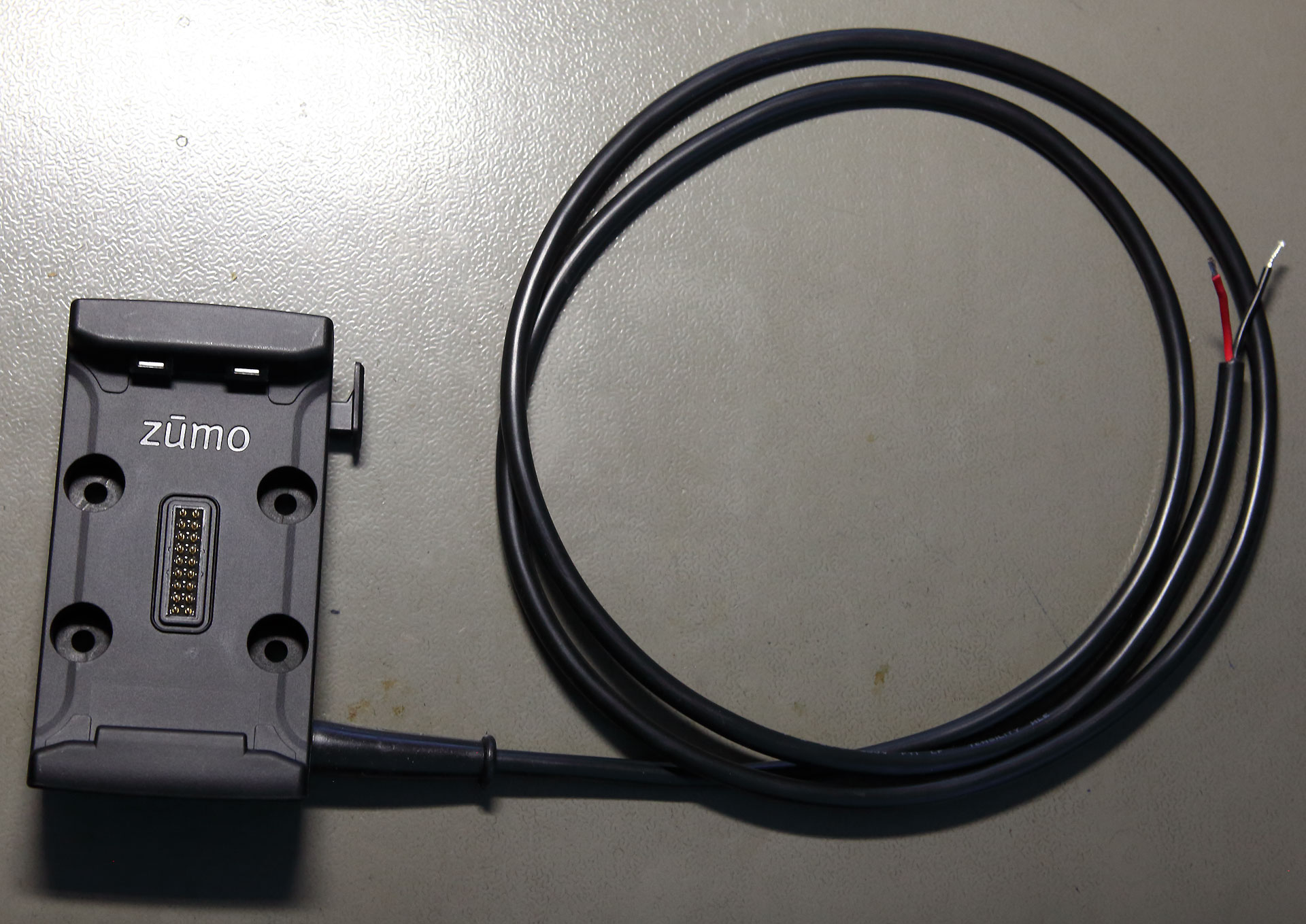
This is how the cradle turned out externally:
And internally:
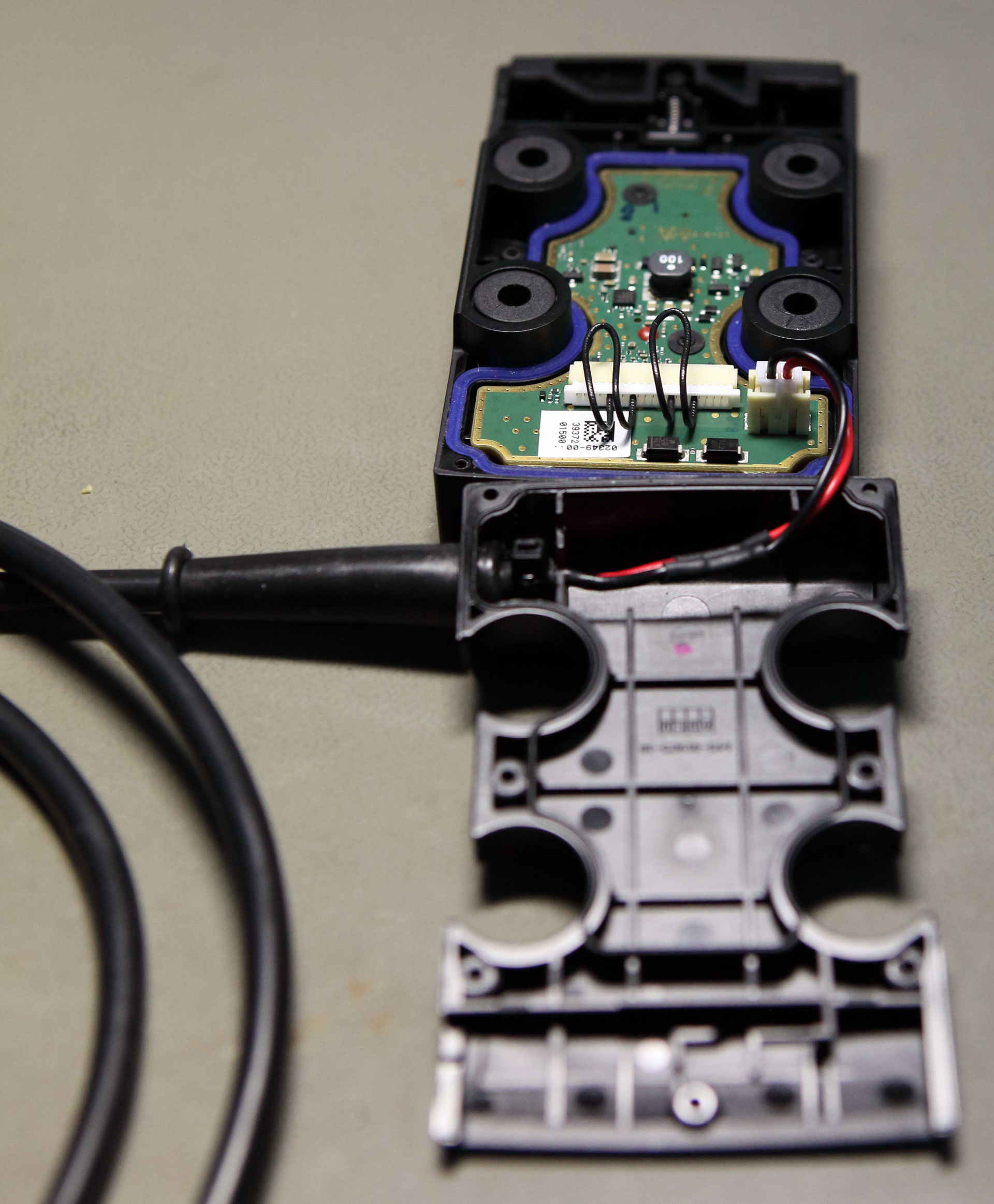
I even made the loopback mentioned above for the audio switches, so I was able to verify that those JST SH connectors were a perfect fit into that 20-pin connector. However, based on the information on the advrider topic, I guess that there are no practical problems even without this loopback.
Unfortunately, there is little room for a strain relief, but two small zip- ties should work adequately, considering the cradle is more or less a fixed installation on my 1190 Adventure. This is probably more of a concern on a handlebar mount where cable moves, but I guess that even there it would not be a big problem, if the cable is tied to handlebar and other cables and hoses.
I still need to put some kind of sealant to the cable entry to prevent water intrusion into the cradle, and to prevent the cable from rotating (I think that the zip-ties will stick on the sealant and do the job). My other highly preferred criteria is that the sealant should be removable with reasonable work (like the original stuff) so that cable replacement is possible should that ever be necessary.
It turned out that MG chemicals had some very good products for this kind of application and my requirements (at least according to the description, like RTV 12) but they seem to be hard or impossible to find here in Finland, so I probably go with Loctite 5145, which is a 1-component RTV silicone suitable for electronics (no corrosive acids).
I also took a brief look at the power supply on the PCB. It seems that it is based on Linear Technology (to be aquired by Analog Devices) LT3480 chip, in DFN package. Package marking identifies the chip as "LCTP".
The Loctite 5145 worked quite well for cable entry sealant, but I could have used smaller extruder nozzle to get to small cavities. But it worked quite nicely with accompanied nozzle and a piece of wire which I used to push the sealant to cavities which could not be filled with the nozzle. Maybe some glue dispensing syringe with small diameter blunt needle would have been better.
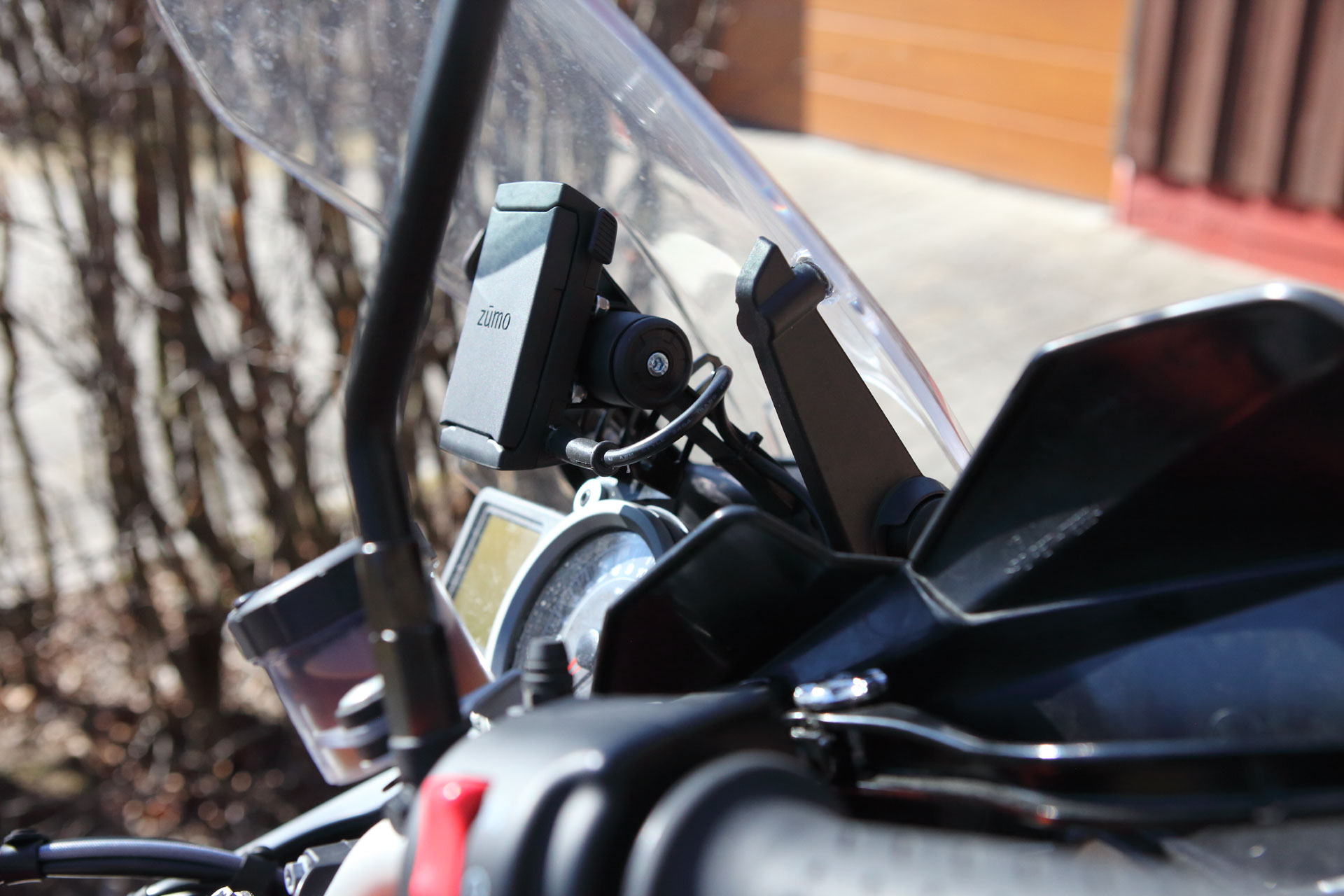
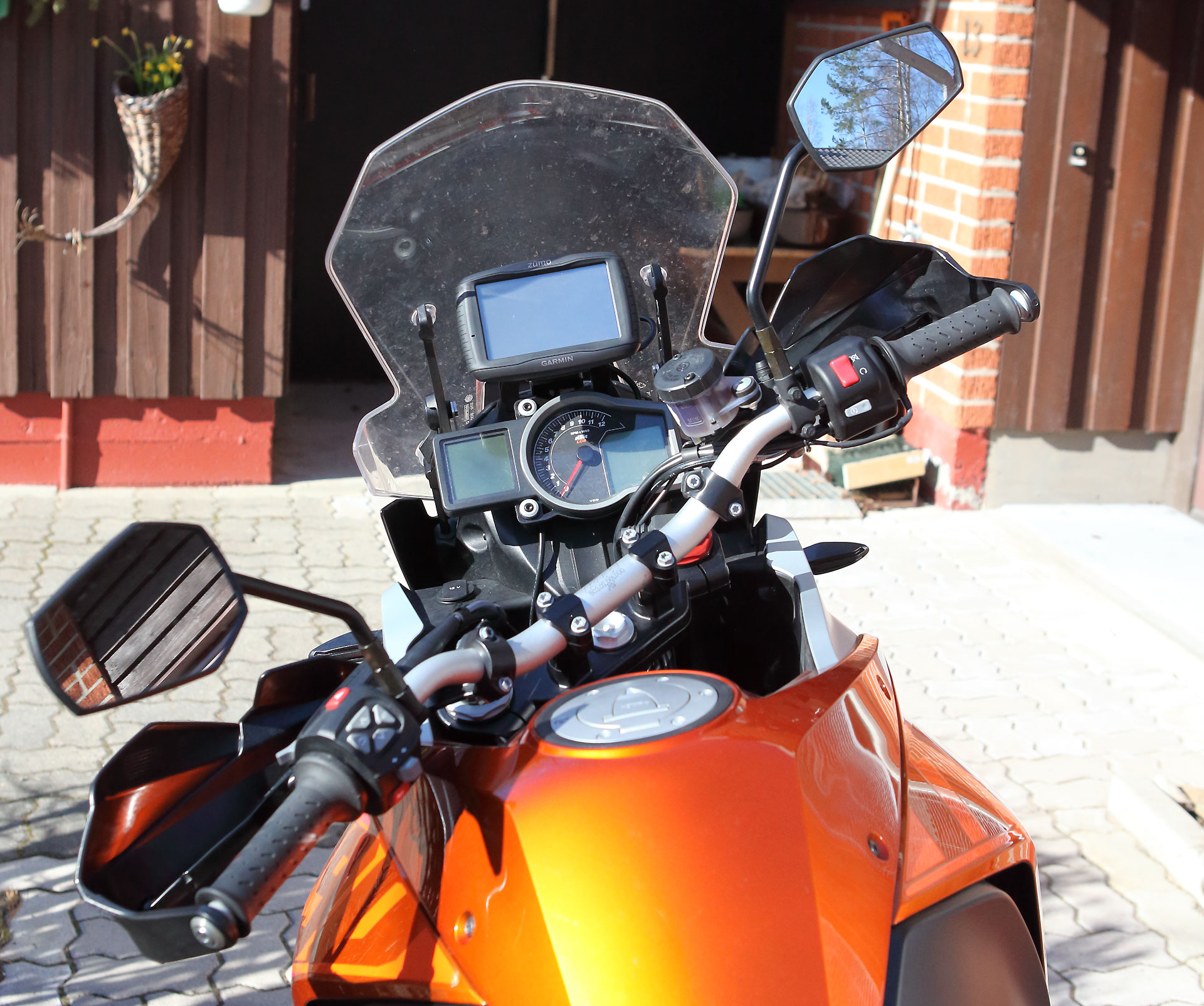
The 1 meter cable turned out to be in fact to be 1.2 meters, so for this particular install, I cut about a half of the length off, so about 60 cm was enough for me. I attached the cable with some slack on the cradle end to KTM powerparts holder arm with a zip-tie and routed the cable behind the dash. See below for pictures of the install.
Here are some pictures of the crate installed to my bike.


Last updated 2017-05-01
© Janne Ahonen 2017-