If you have used conventional 1:10 oscilloscope probes to measure logic signals, you probably know that they have several limitations when edge rate falls. As logic signals get all the time faster, those ordinary probes become less and less useful. The main problem with 1:10 probes is their capacitive loading. At DC, the input impedance of 1:10 probe is 10 MΩ. 10 MΩ is a good thing when measuring high-impedance DC circuits like vacuum-tube amplifiers. For digital circuits, this figure is meaningless. It is the AC-loading which matters. Typical load capacitance value for 1:10 probe is 10-20 pF. At 100 MHz and 10 pF, that equals to 159 ohms. At 1 GHz, impedance is only one tenth of that figure, 15.9Ω!
Another problem is that when the ground clip is used, it forms a very high inductance loop which resonates with the probe capacitance. A result is seemingly high over- and undershoot. Probe banner bandwidth is never measured using the ground clip. Instead, it is connected to BNC with special adapter which connects the ground at very end of the probe (360° shield connection), minimizing the inductance and maximizing the bandwidth.
Then how can you estimate required bandwidth based on the rise time? Easy. For the trapezoidal waveform, required bandwidth is just 1/(Π*tr) or about 0.3/tr. Tr is in seconds and bandwidth is in Hz. For example 1 ns edge requires 320 MHz of bandwidth.
Fortunately, there is a good and cheap alternative for those probes. All you need is 50Ω coaxial cable, a 0.25W 1 kΩ resistor (through-hole 1% one will do just fine), a BNC- connector (or whatever you'll have at the scope end) and optionally 50 Ω inline terminator at the scope end (if not available on the scope internally). For the coaxial cable, usual cable type alternatives are RG-174, RG-316 or RG-178. RG-174 is probably a good choice because it is not very thick, but RG-316 tolerates soldering much better and has slightly lower loss or RG-178 which has smaller diameter thus more flexible but has higher loss at higher frequencies.
Put the BNC connector at the other end of the coax, and shorten and connect the 1 kΩ resistor at the other end of the coax. Shield the connection between coax center conductor and resistor with a suitable heat shrink sleeve. The probing end should then look something like this:
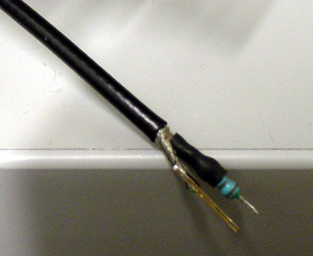
I first noticed this probe in a book from Howard W. Johnson and Martin Graham, High-Speed Digital Design, A Handbook Of Black Magic. According to this book, 0.25 W resistor has about 0.5 pF of shunt capacitance. That makes a huge difference to an ordinary probe.
The terminator should be preferably internal one on the scope, but if one doesn't have such a scope, then next best thing is the inline terminator:
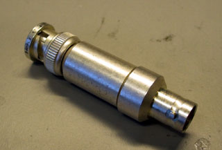
For readers in Finland, this particular TE inline terminator 1-1478207-0 is ELFA P/N 46-295-80, which is no longer available. Huber+Suhner 6701.01.B looks like to be a replacement. Digi-key P/N 501-1036-ND is similar.
Cheapness of this DIY-probe makes it very suitable for the situations where you might need to abuse a probe, during some environment or vibration testing etc. Few coax cables and resistors do not cost very much, but try same with commercial active probes! I have found that if you have a bus what to probe for a some time, it is best to solder the probes to the board. That way, the risk of damaging the board with loose ground clip is much less likely. Again, this coax probe is much more suitable for this kind of application than ordinary ones.
Another application might be a DIY logic analyzer probe. There are several FPGA-based logic analyzers around, but they would also need proper probes for the signals. With suitable front-end (comparator, LVDS/PECL receiver etc.), this probe would be an excellent companion for a DIY logic analyzer. A good signal integrity is a must when working with a logic analyzer, because you can't see the analog waveform like on the scope.
The drawback of this probe is that most scopes do not allow setting of arbitary attenuation of the external probe (Not even on my now obsolete, semi- expensive Keysight MSO6034A!). At best you can get a 1:20 setting. But that does not affect very much, at least if you are just measuring signal integrity or debugging a digital bus. Of course, you could use a E96 953 Ω resistor and get 1:20.06 attenuation.
I measured the frequency response (S21 and S11) of the probe using a HP 8753D Vector Network Analyzer (VNA), from 30 kHz to 6 GHz. A VNA is a combination of a tunable RF signal source and a coherent receiver. Coherent basically means that the signal source and the receiver are in the same phase and the receiver is capable of detecting the phase shift regarding to the output signal in addition of the magnitude (=vector). A VNA also has a bridge at the both ports which makes it possible to measure also the reflected signal. The measurement of the reflected signal is necessary for measuring impedance matching, or S11. For this study, only magnitude was measured so a scalar network analyzer would have been enough.
For documentation, I used quick-and-dirty LabView VI which performed a single sweep on the VNA via GPIB, downloaded the results and saved them to text file for plotting using GNUPlot.
The frequency response was measured by connecting a 50 Ω terminated stripline fixture into port 1 and then probing at the stripline. Probe output was connected to the VNA port 2. As the VNA ports are internally terminated into 50 Ω, there is no need for the external terminator.
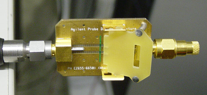
The measuring fixture with terminator resistor (Keysight E2655-66501):
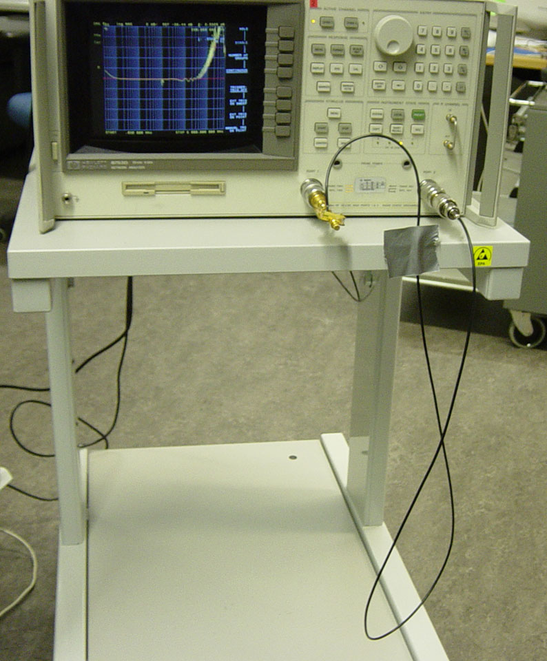
And the measurement setup (note the duct tape). This also shows how the probe looks like overall:
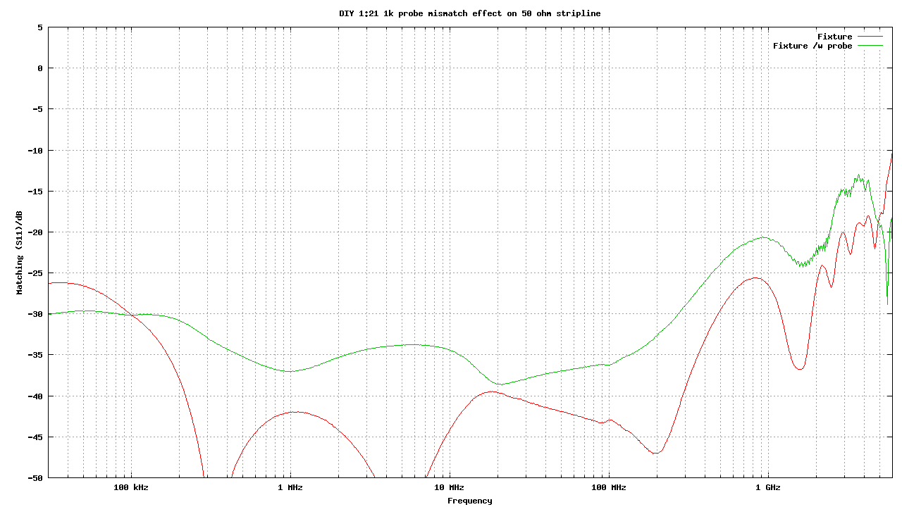
And here is the result:
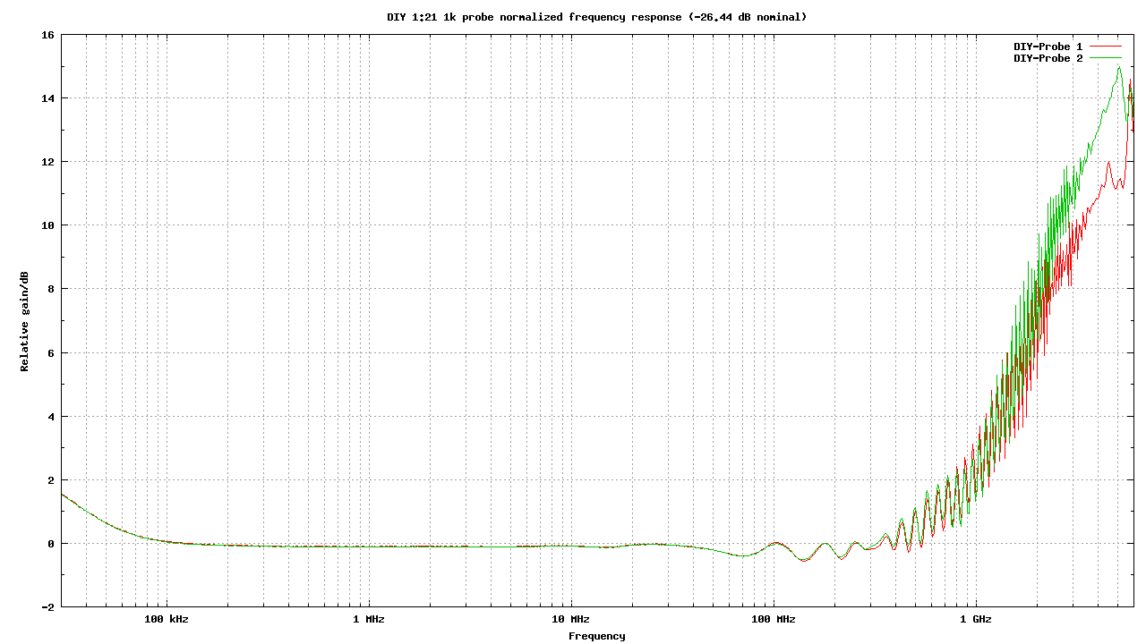
There is a strange rise of the response in the low end. I think that it has something to do with the VNA itself. Maybe the AC-coupling is doing something strange. At the upper end, the response is usable to about 1 GHz. Not bad for such a simple probe. I measured two DIY-probes for some estimation of repeatability. They both show a remarkably similar behaviour. The small ripple is probably because the coaxial impedance and VNA port 2 impedances are not perfectly matched. This setup requires that "receiving" end must be perfectly matched, otherwise reflections will occur.
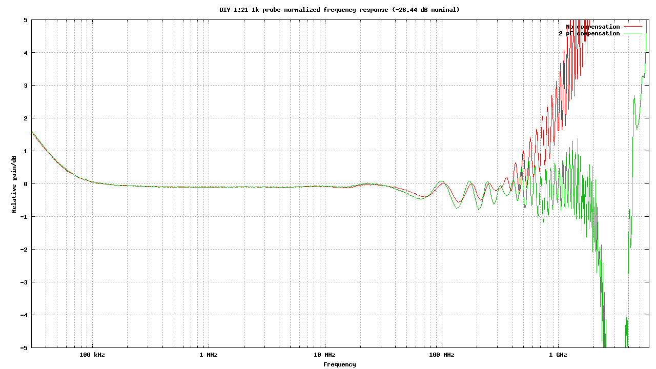
Next, I tried to tweak the probe if the bandwidth could be increased even more. I connected a 2 pF 0805 SMD ceramic capacitor after the 1 kΩ resistor in parallel with coaxial feed, or just where the coax begins. That made the bandwidth usable to about 2 GHz! I think that really not bad performance at all for this kind of construction. The compensation capacitance value could be a little smaller, I think that I'll investigate more later. Also the coaxial termination would need improvement, the pigtail is not the best method above 1 GHz. However, one point about this probe is its simplicity.
And how this probe affects the signal travelling on the fixture? For that, I measured the probe effect on the S11 (reflection) using VNA. Note that the VNA is not calibrated in this measurement so the actual figures are not accurate, but nevertheless the effect can be seen. The match still remains quite good. To set the scale as VSWR, -20 dB on the scale means about 1.20 VSWR. -30 dB is 1.06 etc.
What kind of performance can be expected from this simple probe setup? For that I made a comparison against Keysight 7 GHz 1134A Infiniimax probe amplifier with E2675A differential browser head, which certainly qualifies as a high quality active probe. It is also very expensive item for just casual hobby use, about $10k! The price is certainly not much if you must have very accurate measurements without any doubts. But I know that it makes company managers cough or change the subject when you say that you'll need a few of those probes for the measurement...
The signal source here is an Altera Cyclone II FPGA which has very high edge rate IO:s, when set to full current strength. The edge rate can easily be around 100 ps, which is very fast and needs considerable care. Note that the edge rate is not affected at all by the frequency which the signal is switching, it just sets how often the transitions will occur.
These measurements are taken using 4-channel, 6 GHz Keysight 54855A Infiniium oscilloscope.
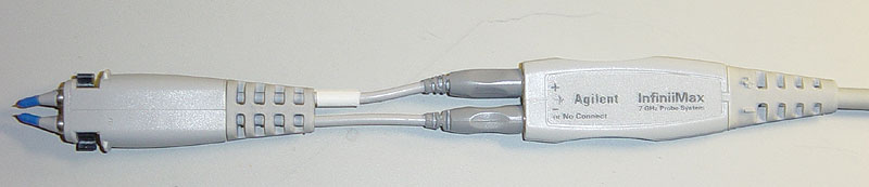
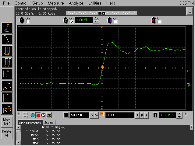
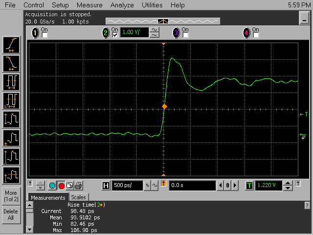
Here is a comparison between 7 GHz Agilent Infiniimax probe and this DIY-probe:
| Agilent 7 GHz Infiniimax | DIY 1k Probe |
|---|---|
|
| |
As expected from the frequency response, there is some additional overshoot on the rising edge. The apparent rising edge is somewhat faster on the DIY probe.
This page last updated on 2021-06-13
© Janne Ahonen 2009-2021